
This guide is for flashing and assembling a Mayumi V4 modchip. Required parts
- PIC 12F508-I (letter is important as it need to be rewrittable)
- 150ml SOP8/16 socket
- XGecu Pro T48 programmer
- PCB
- 100nf 0603 SMD capacitor
Start up Xgpro (tested with v12.66) and connect the T48 programmer
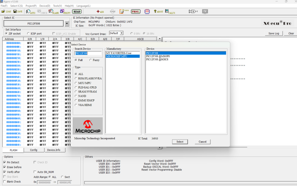
Ensure the right chip is selected by clicking in top-left button that says “Select IC” and typing PIC12F508 in the search box. From there, Manufacturer is Microchip and Device is PIC12F508
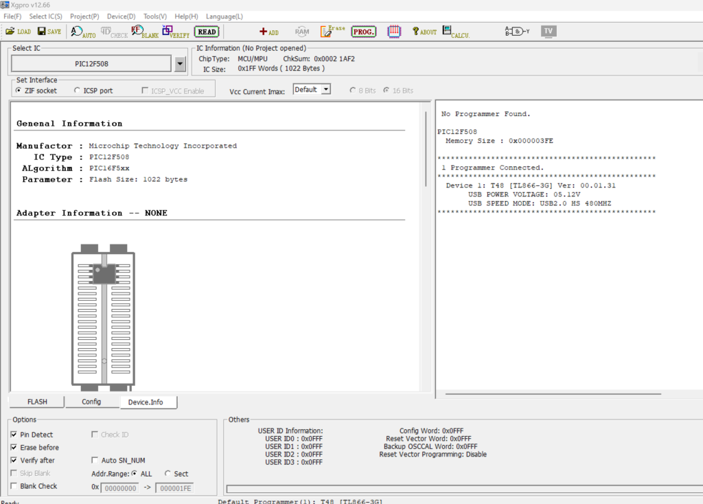
Click Device.info tab on bottom left and it will show how to insert the adapter and the chip. In order to insert the chip in the adapter, push gently down the top black plastic, which will withdraw the contact pins, then drop the chip with tweezers, and then release the black plastic piece
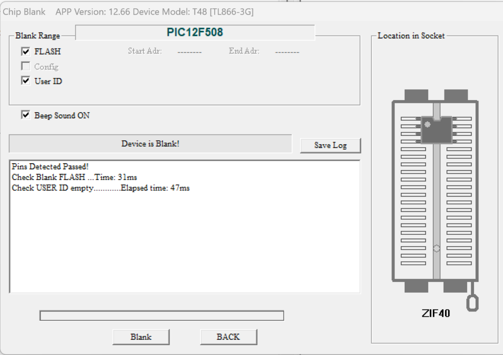
Check that the chip is blank. For that, choose the icon “Blank” in the icon bar at the top. In the dialog box select “blank” and it should beep and say “Device is Blank”. If the device isn’t bank, get out of the dialog box and select “Erase” from the icon bar. Once is erased, check again that is blank and it should be this time.
Load the HEX file by clicking “load” in the icon bar. There are three HEX files depending on the region, just choose the one from the console you are going to mod. Ignore the memory error.
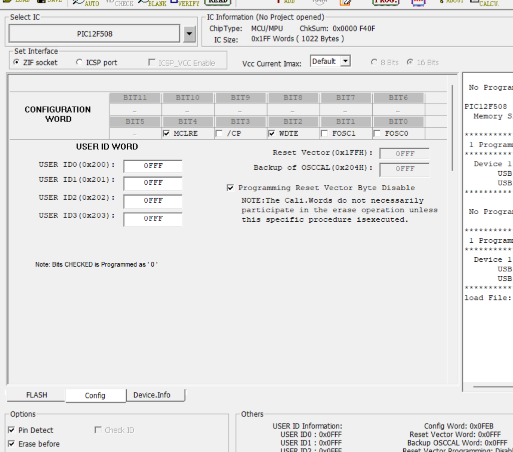
Go to the “Config” tab and make sure that the MCLRE and WDTE checkboxes are checked.
Go to the Program icon in the icon bar. Click “Program”. It should result in a success.
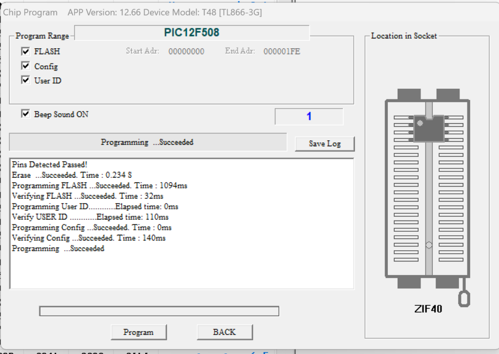
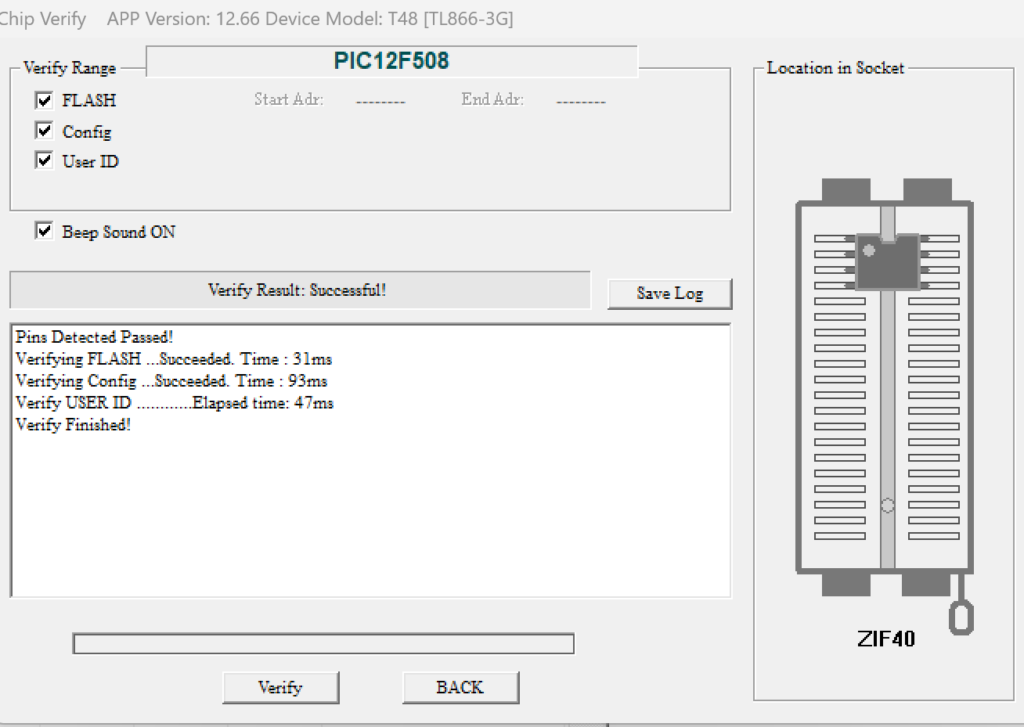
Let’s verify that the the flash went well. Reload the HEX file by clicking in the Load icon again, choose your HEX image, then ensure that those tickboxes are clicked in the Config tab, and then click “verify” in the icon bar. That should compare the chip image and the HEX file that you have loaded and confirm that they are the same. That ensures the flash went well.
For an extra check, you can also go to the File menu, select “Clear all Buffer”, then click on READ in the icon bar, and it should load the chip and you should be able to see “Mayumi04” at the top.
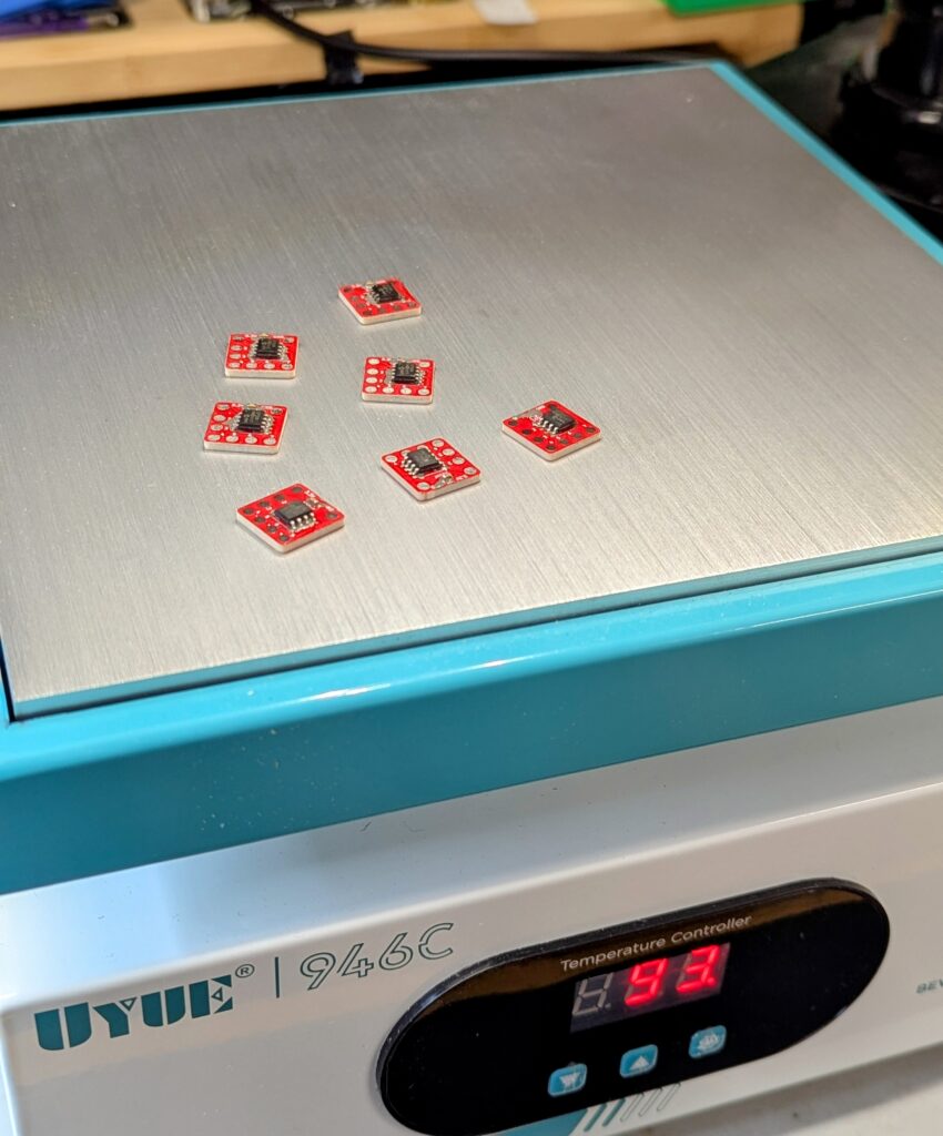
The PCB only carries the Mayumi chip and a 100nf capacitor. Solder and done!
Reference material
- https://www.youtube.com/watch?v=gB3ejXT9Dpc