
The serviced purchased was:
- PS1: Installation of a Mayumi v4 provided by Topvint and a DFO provided by Consoles Unleashed
- Mega Drive 1: Installation of a triple bypass provided by Retroupgrades
Playstation 1
The console was a PU-20 revision 70003. Tested in advance to make sure that CDs are reading well. The installation of the Mayumi chip is done on top of the motherboard.
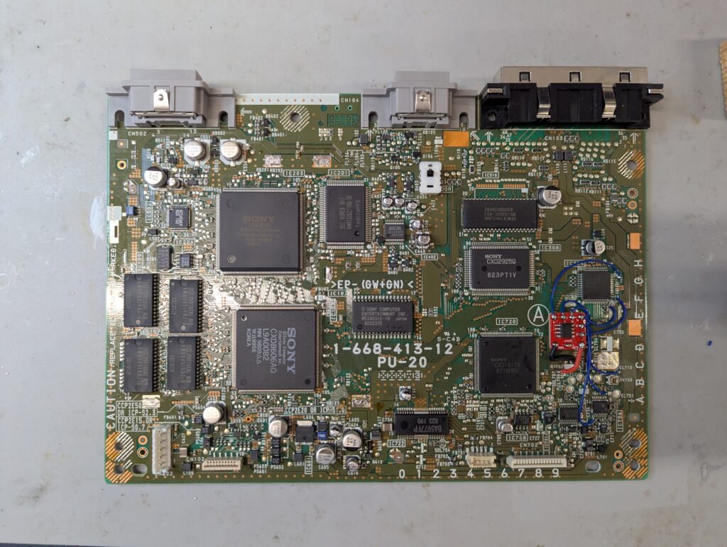
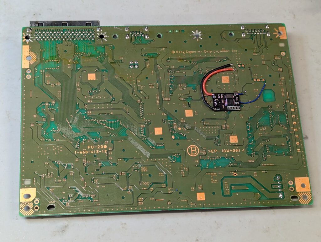
The installation of the DFO is done on the underside of the motherboard. First it needs the removal of resistor nearby the main chip, and for that the shield needs to be removed as well
Testing with imported games and a SCART RGB cable (as confirmed by the customer having the same setup at home)
Mega Drive 1
This is a VA0 Japanese Mega Drive (first ever revision), and has been modded in advance with a region-free mod. This involved the removal of the LED and replaced by a new LED that displays a different colour depending on the region. The region is changed by pressing the reset button during a couple of seconds. Operation was confirmed before starting the modding using a DIN 8 SCART cable.
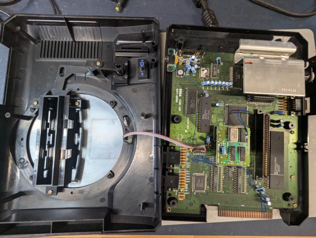
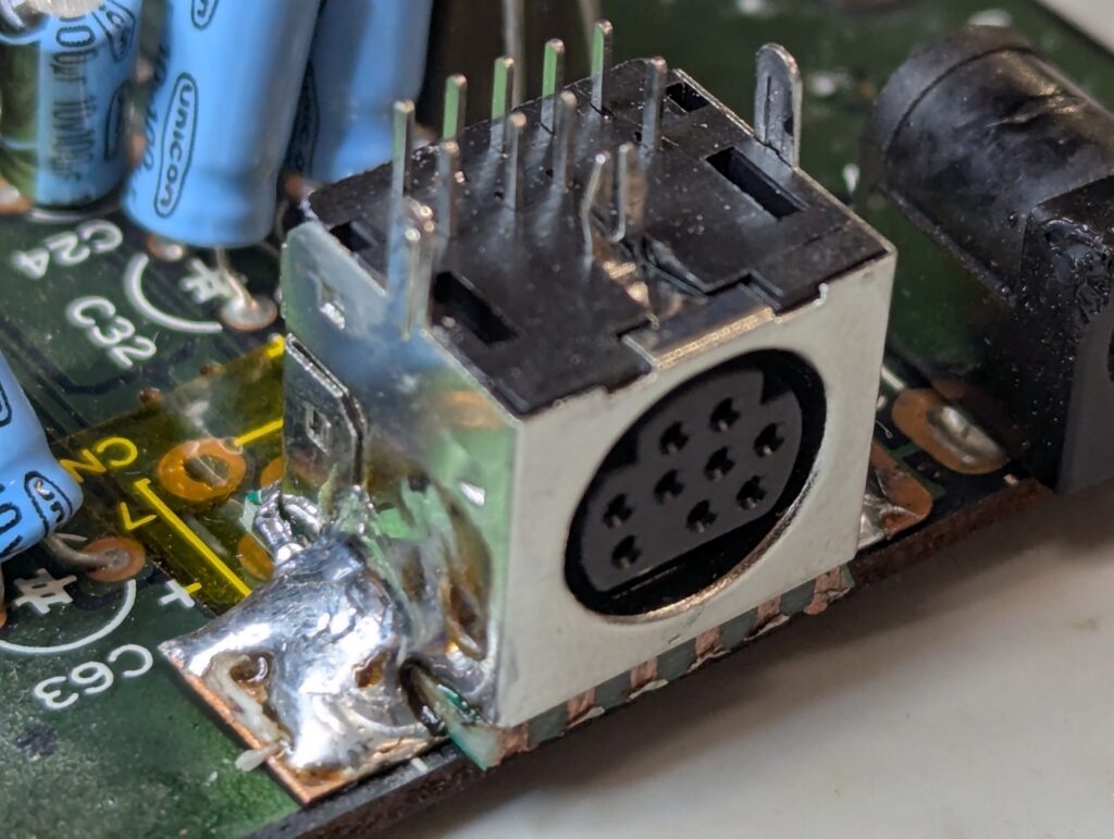
A triple bypass mod in a Mega Drive 1 normally involves replacing the RF module with the new DIN 9 connector. However, this revision doesn’t have an RF module. Therefore the only possible location of the new DIN 9 connector is to replace the old DIN connector. The Triple Bypass PCB slots on top of the DIN 9 connector, so it is not possible to keep the old connector in any case for this mod.
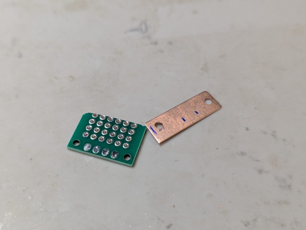
Unfortunately the interposer PCB that is provided by Retroupgrades is only useful for installing the new DIN connector in place of the RF module. I had to create my own interposer by combining a piece of copper and a cut breadboard, so that the connector could be place in the middle of the larger old DIN connector hole in the back of the console.
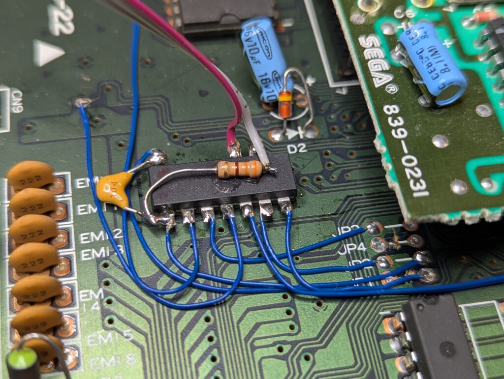
Once the DIN 9 connector was in place, it was time to install the mod. The first step is to lift pins 27,28 and 29 from the main chip, which carry the video. Usually Retroupgrades provides a VDP’2’3BP board for easy tapping into the RGB signal, but they run out and provided a more generic board which is harder to install and doesn’t containt he pull-up resistors. Overall the installation looks less tidy because of that
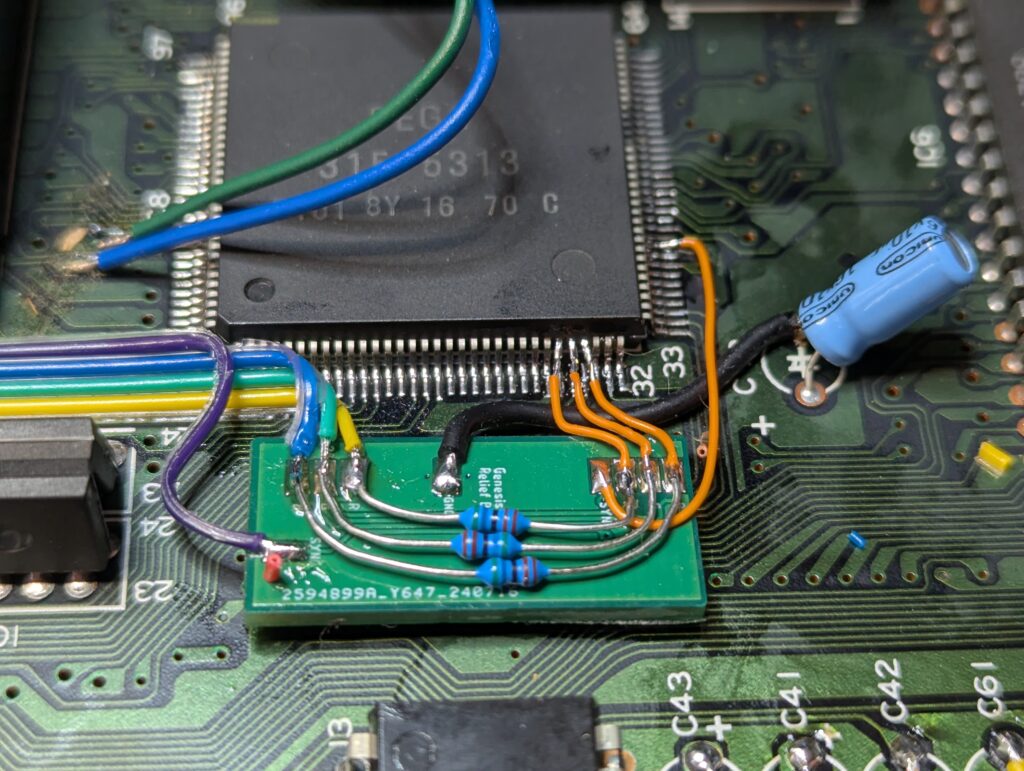
Next step is the audio. For that, 7 capacitors needs to be removed from the motherboard and wires attached to them so that the amp used is the one from the TBP board.
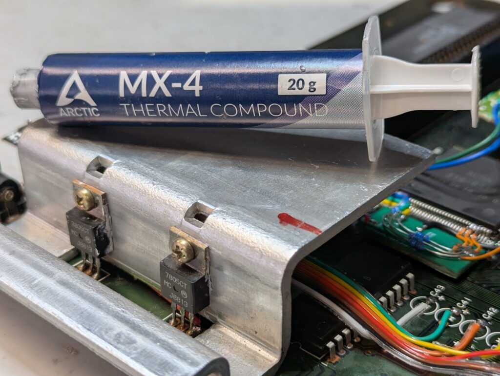
The console was put back together and tested with a DIN 9 RGB cable (Retroupgrades sells one). I also put back together the heatsink with new thermal paste. Ideally the voltage regulators could have been replaced, but those are included in the recap service.
Something to note on this console is that not all the screws were included. Notably, the leftmost cart slot screw was missing, and the pole underneath broken (so I could not put a new screw). Also screws in the front of the console were missing, so the motherboard is mostly attached to the back of the shell. Please be gentle when inserting and removing controllers as well as carts.