The serviced purchased was the installation of a N64RGB mod 2.1 sold by Retroupgrades.
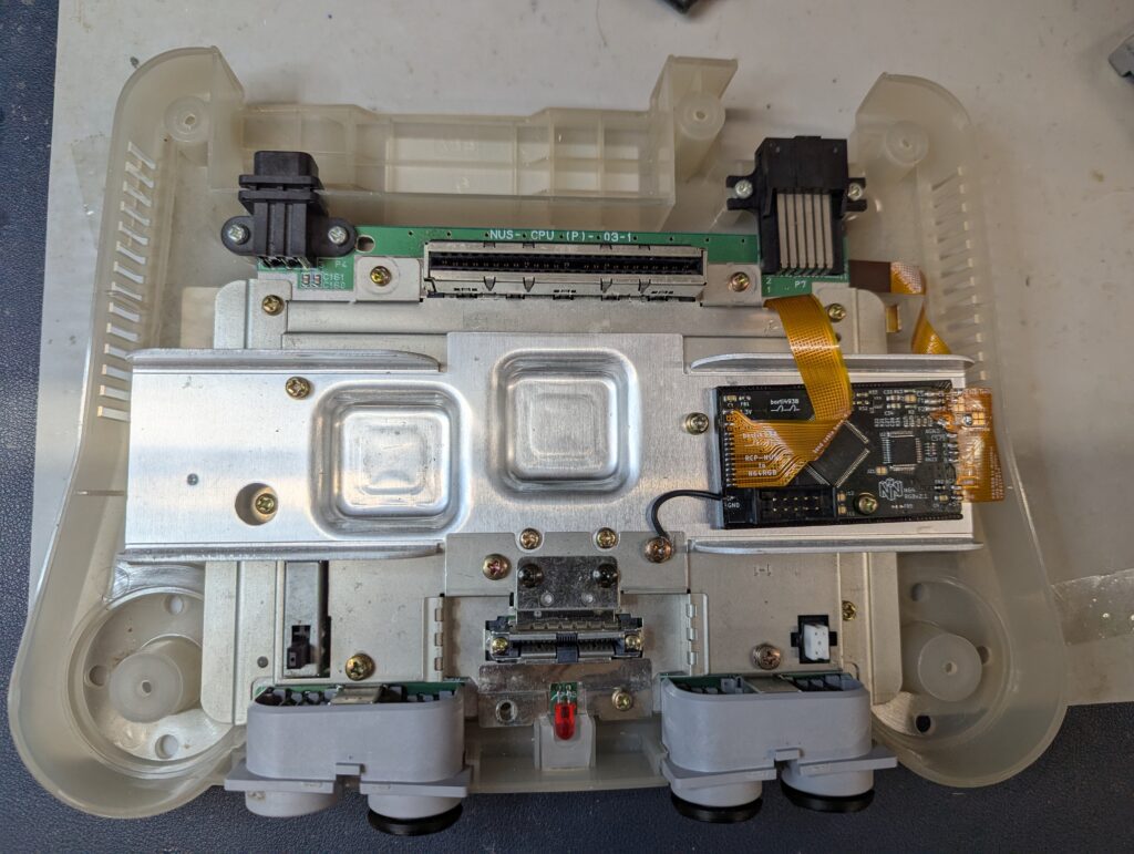
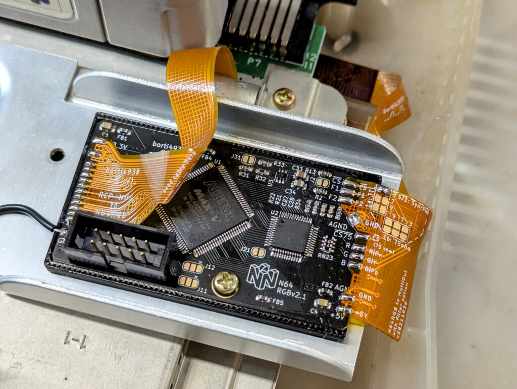
The modkit comes with two flex cables with a PCB and two flex cables. One of them should be soldered to the RCP-NUS chip, and the other one to the back of the multi-out connector. Both of them then get connected to the PCB, which gets mounted on top of the shield.
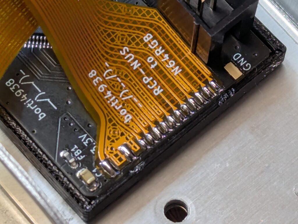
The only preparation for the mod was to bend the top shield at the multi-out connect level, to allow the first ribbon cable to come this way. After this, I just soldered the first ribbon cable between pins 8 and 28.
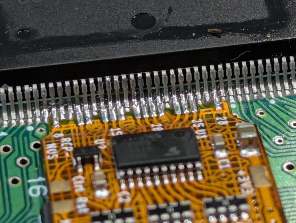
The flex cable has three points to solder: 3.3V, Reset and Ctrl. The console is a NUS-CPU-P-03 model, which is somewhat an unusual board revision. While the 3.3v and Rst connection points were standard, the controller one wasn’t and I had to poke around a bit to find a via near the PIF-NUS chip
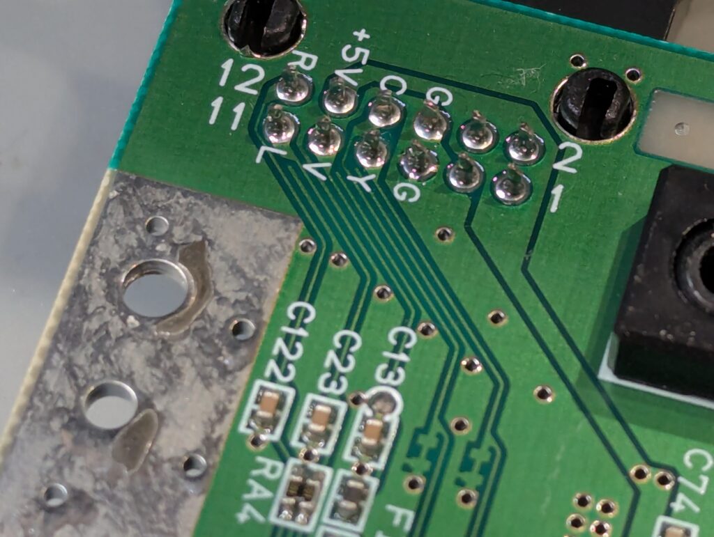
Next up was to wire the other flex cable to the back of the multi-out. Pin number 3 is meant to be disconnected which it is in this revision.
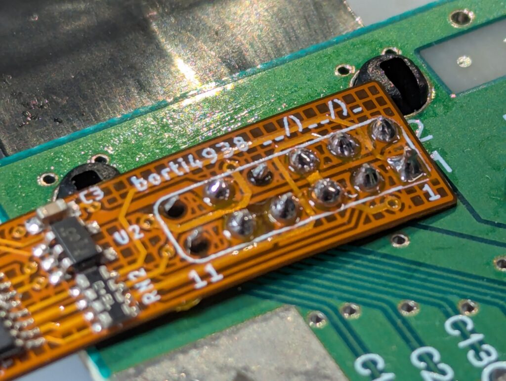
I installed the PCB on top of the shield using the 3D printed adapter and proceeded to solder the flex cables to the PCB. The ribbons had clear points for bending into place which is really important to then align the solder points to the PCB
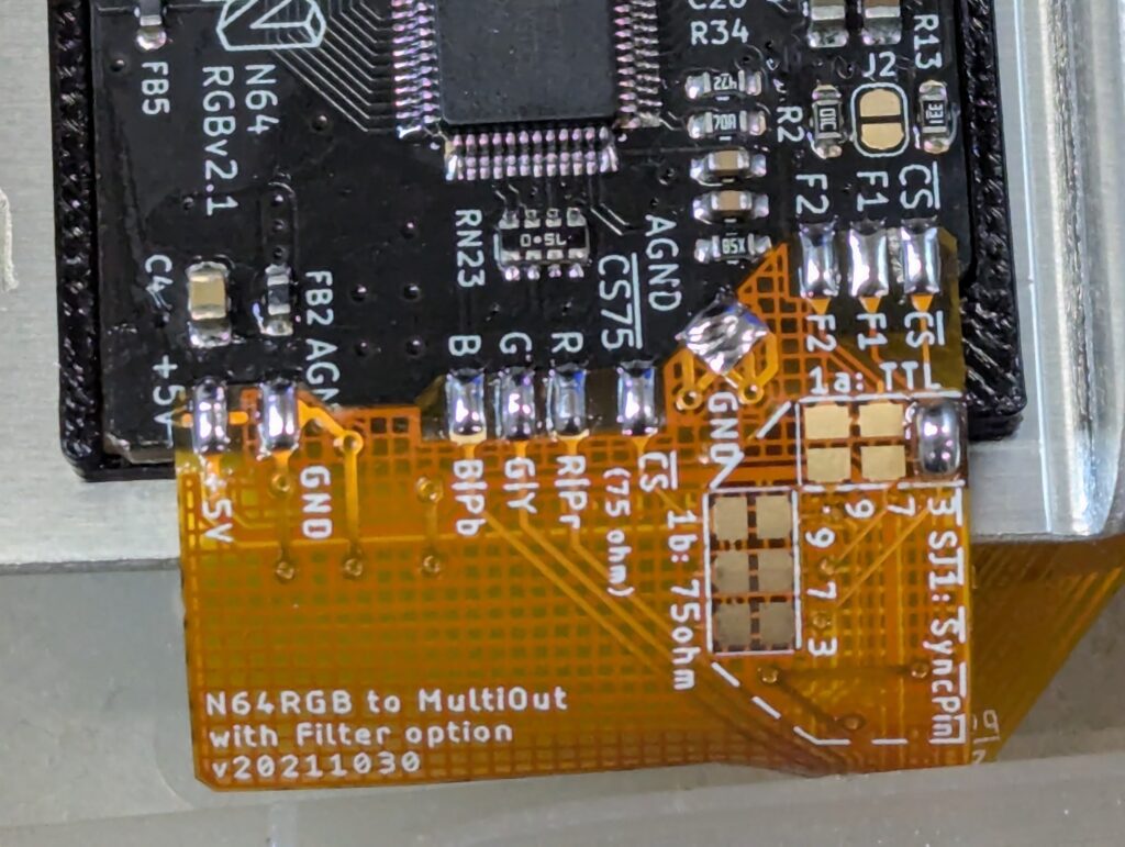
This is a universal board, and has a number of jumpers for various configurations of cables and hard-wired options. This page has a clear list of options. The customer wanted to use a Rad2X multi-out to HDMI adapter. Upon discussing with the modkit seller, the advise was to do a standard install first to test it works, and then change the jumper settings for the Rad2X, particularly because the seller wasn’t completely confident of that particular option. The standard option is meant to use an NTSC SCART cable, with TTL wired to pin 3 of the multi-out. After configuring the mod this way, I successfully tested the console
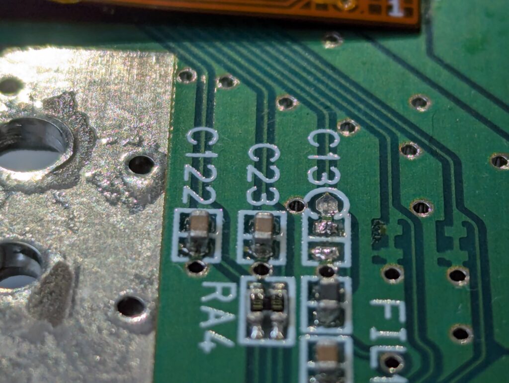
The advise of the modkit seller was to then change the sync jumpers to 75 ohms on pin 9 (1b – 9) as Rad2X uses composite. He also advised to close jumper J31 on the PCB, for pass through at sync (CSYNC 75ohm). Furthermore, he advised to disconnect pin 9 in the multi-out, labelled as “V”, by removing capacitor C13.
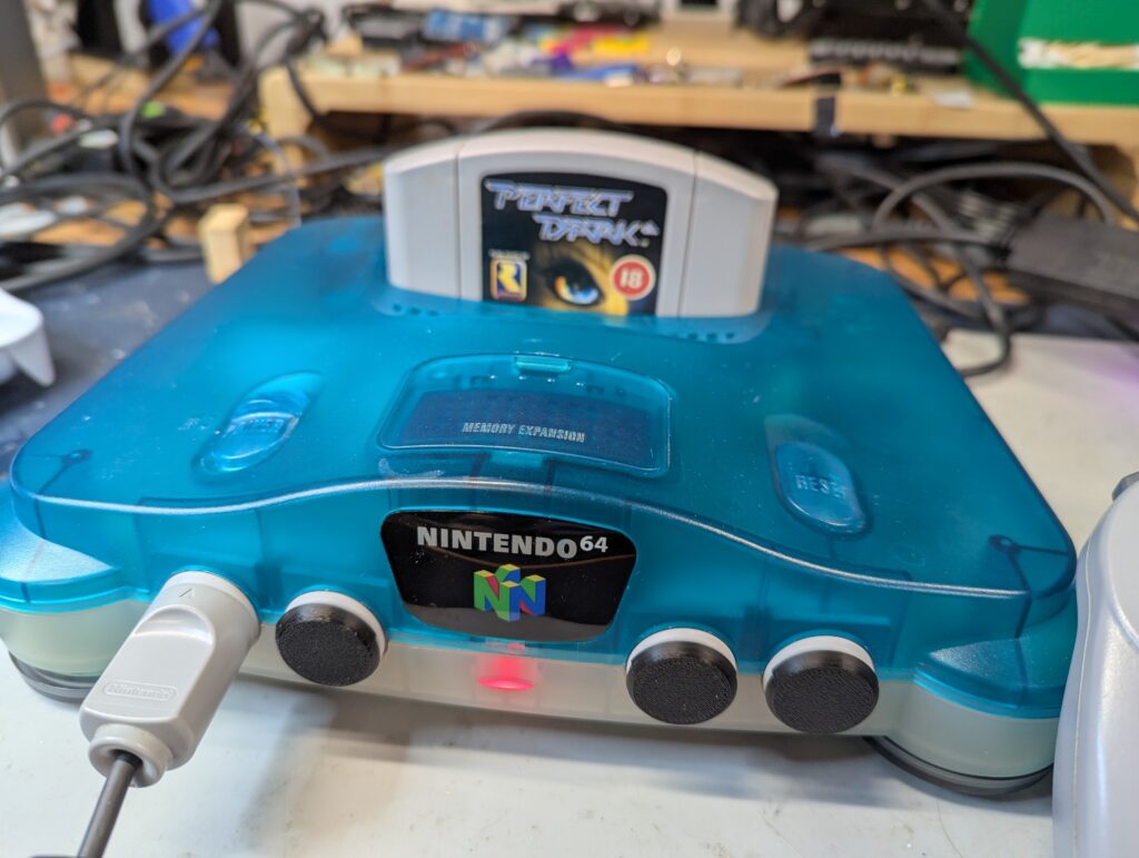
After this the console worked fine with the Rad2x and a mini HDMI cable. It was a matter of assemble it back and play a bit of Perfect Dark 😁