This order was for the installation of a RetroGEM HDMI kit both in a GameCube and a Nintendo Wii
Nintendo GameCube
The GameCube was provided with a custom paint job and a GCLoader instead of the optical drive. The kit provided was a Basic edition. The first step was to prepare the console, which included:
- screwing the external HDMI port to the 3D printed bracket and filing the screw so that is flush with the bracket. There was no screw and nut in the kit that was sent so I used my own
- Trim the metal shield to make space for the HDMI port
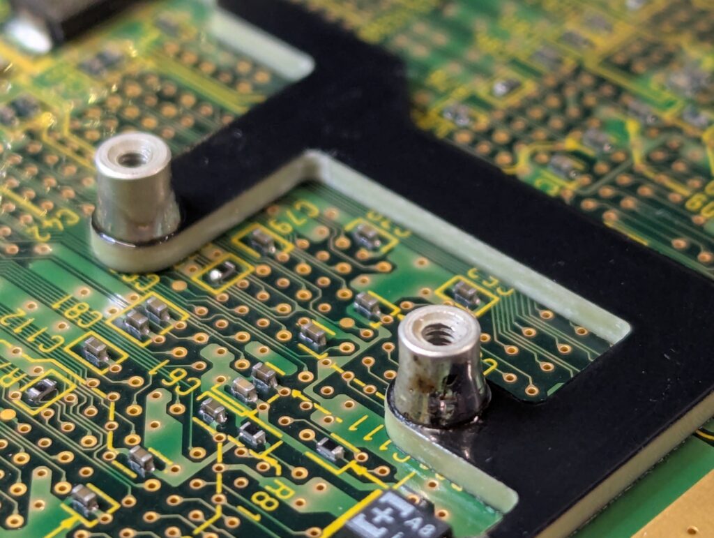
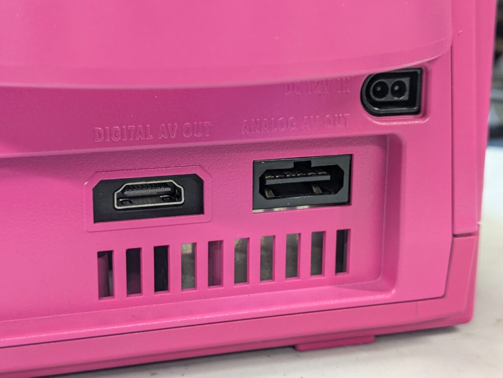
The next step was to remove the digital port to make space for the HDMI port. This is the no-cut version that the customer agreed to. After that, the bracket to install the holder for the GEM PCB was also installed using a few anchor points in the main Cube board. The two metal studs to screw the GEM PCB also need to be soldered in
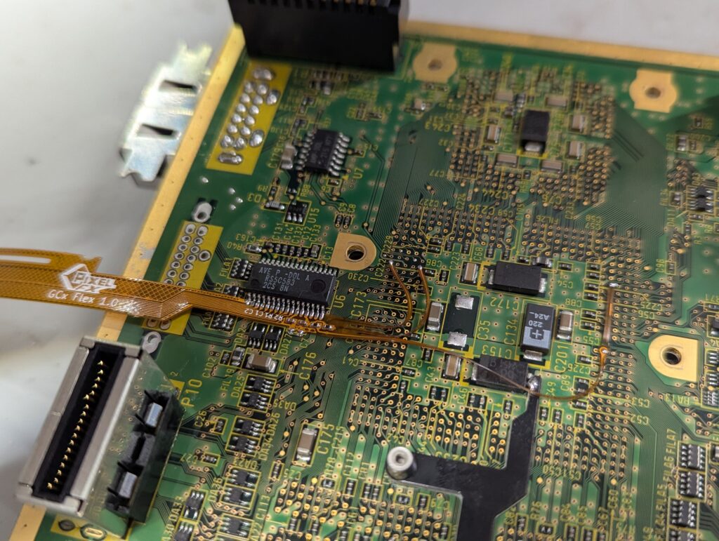
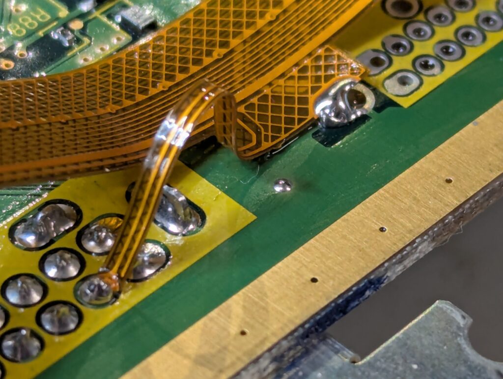
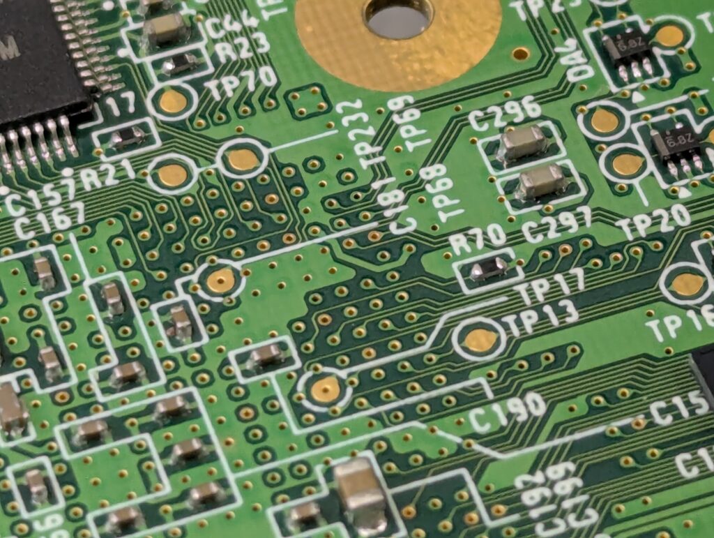
After this, the next step is to install the flex cable and solder it to the main video chip, as well to a few other points in the board for controller input, power and ground.
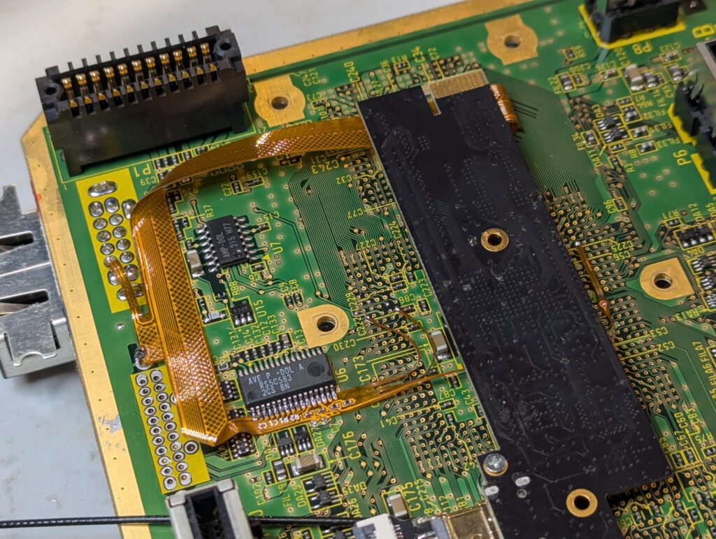
After that, the internal white flex to connect the external port to the internal port needs to be installed and the board to be put back into the shell with the external HDMI port bracket in the right place
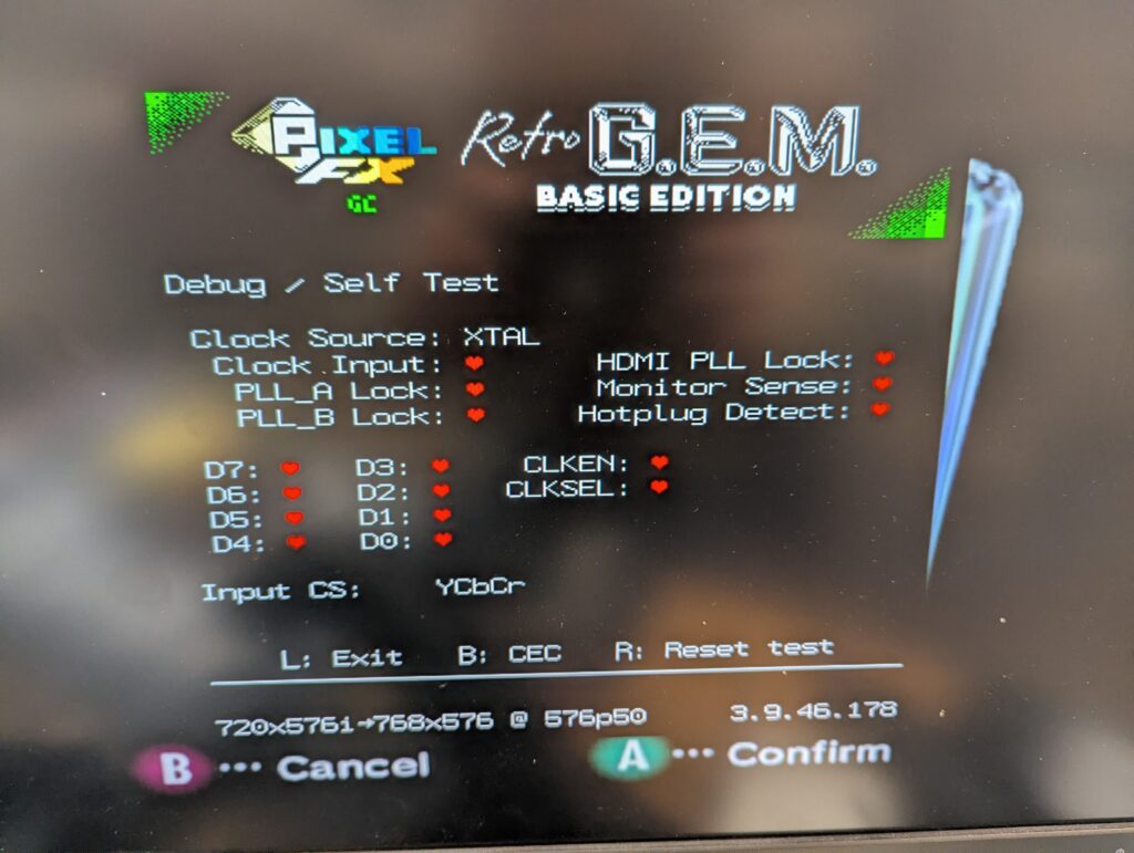
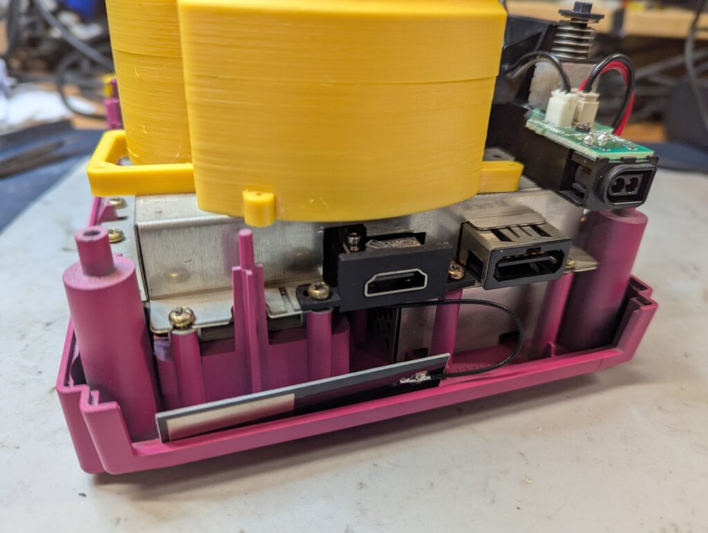
Final tests before putting all back together. Note where the antenna has been left by the back panel. It is not glued to it as that would prevent the console to be disassembled easily, and is also not glued to the metal shield as this will probably interfere with the antenna.
Nintendo Wii
The customer provided a white Nintendo Wii, motherboard revision RVL-CPU-30 which is a 6 layer PCB. The RetroGEM kit provided was a Basic edition.
First step was to disassemble the console, which can take quite a lot of time on itself
As before, next step is to prepare the console. This includes installing the PCB bracket and preparing a couple of solder points for later
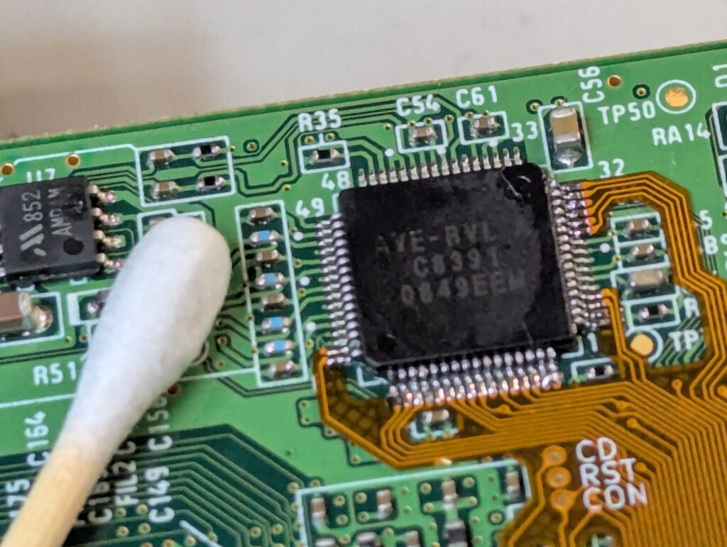
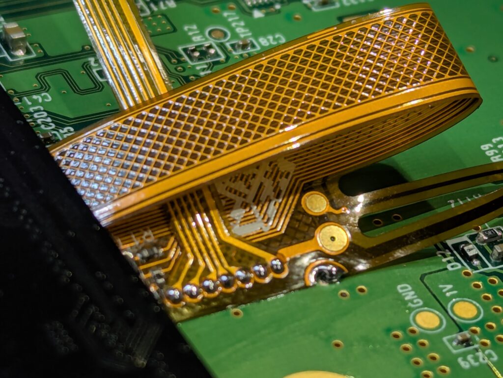
Then is time to install the flex. In this console, the video and audio chip (AVE) is really small and requires careful preparation of the pins and a small soldering iron. After installing the flex, the console should boot with composite, although is important to have the main processor heatsink connected. For this, I used a couple of temporal long screws and nuts. Note how the wireless cards are still plugged in, or the console won’t boot
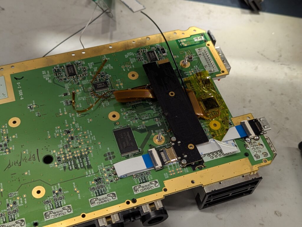
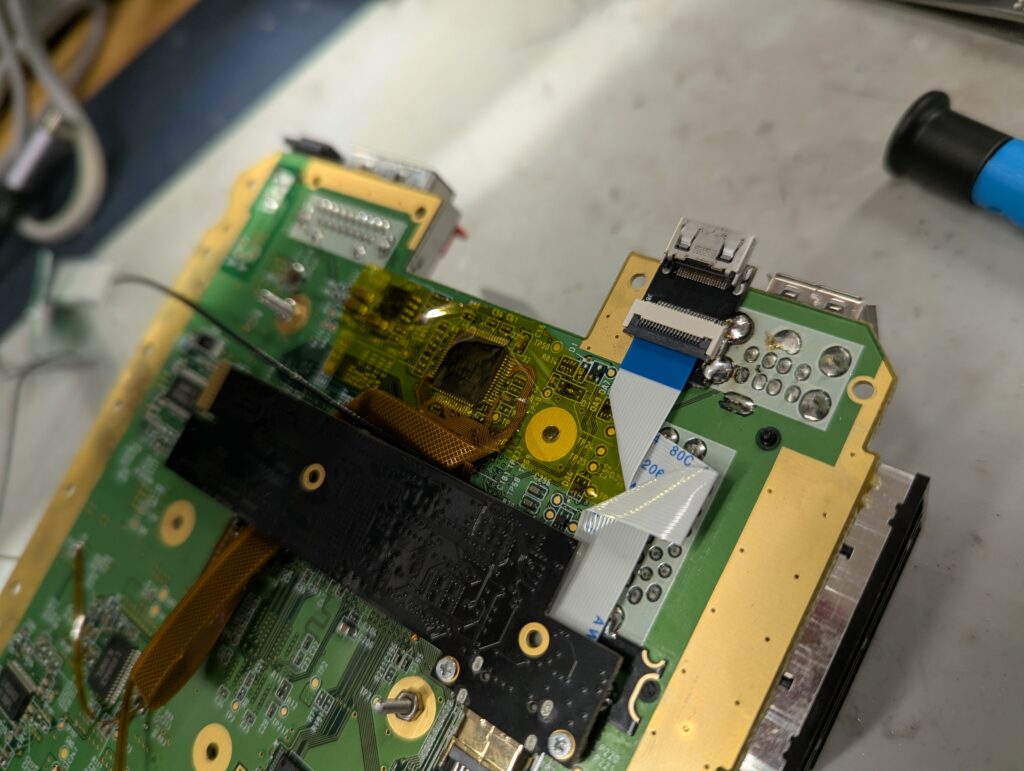
Next step is to install the rest of the solder points and the flex into the RetroGEM board, and then test again. After operation is confirmed, then the external mini-HDMI port needs to be installed by the USB ports, and the white ribbon cable connected to do a final test of the main functionality. Observe the originami of the various ribbon cables 🙂
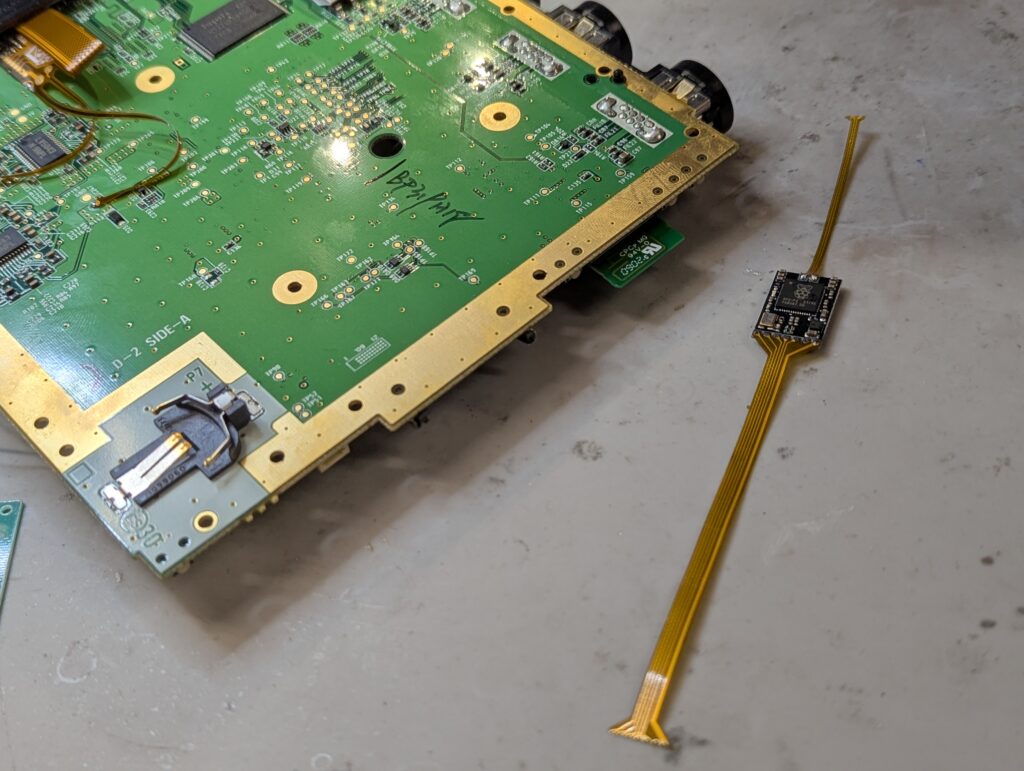
Next is to install the USB sniffer, which allows the GEM to interject the controller presses (something much easier in consoles with a wired cable). This intercepter has a Raspberry Pi microcontroller for the additional functionality. The sniffer is installed to the bigger ribbon cable and to a couple of points on the motherboard.
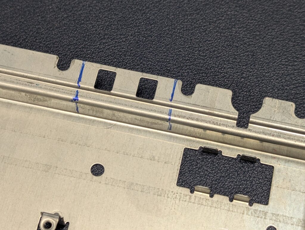
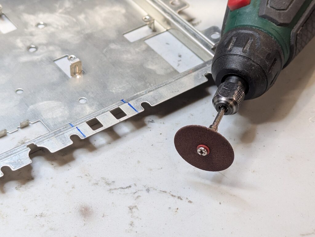
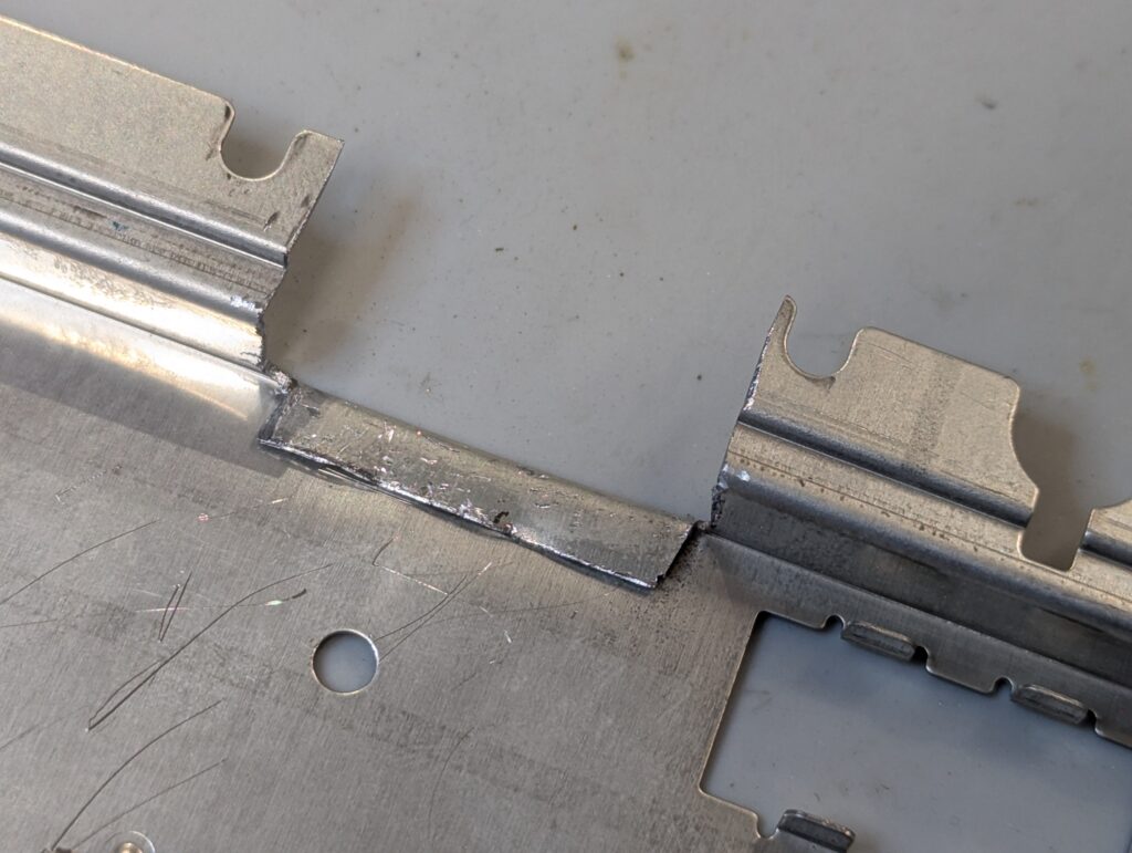
After functionality has been tested, is time to put the Wii together. Firstly however, the shield needs to be trimmed so that it doesn’t clash with the locatio of the external HDMI port we have installed.
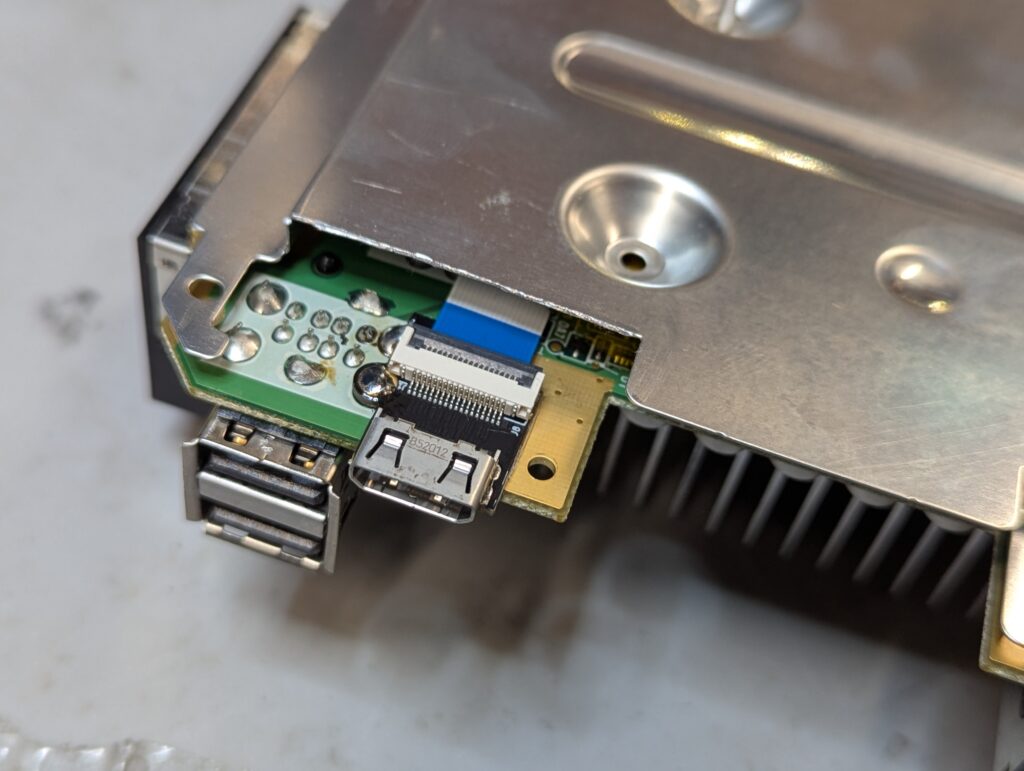
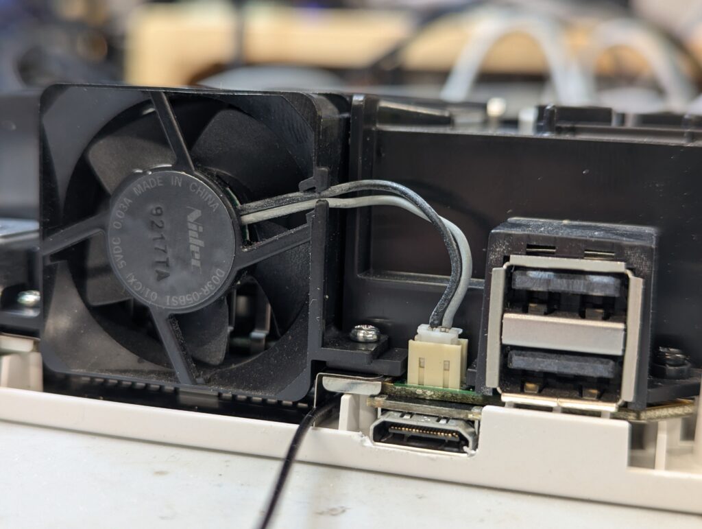
The top plastic shell needs also a small cut to accommodate the port. After that is a matter of testing and ensure everything is good.
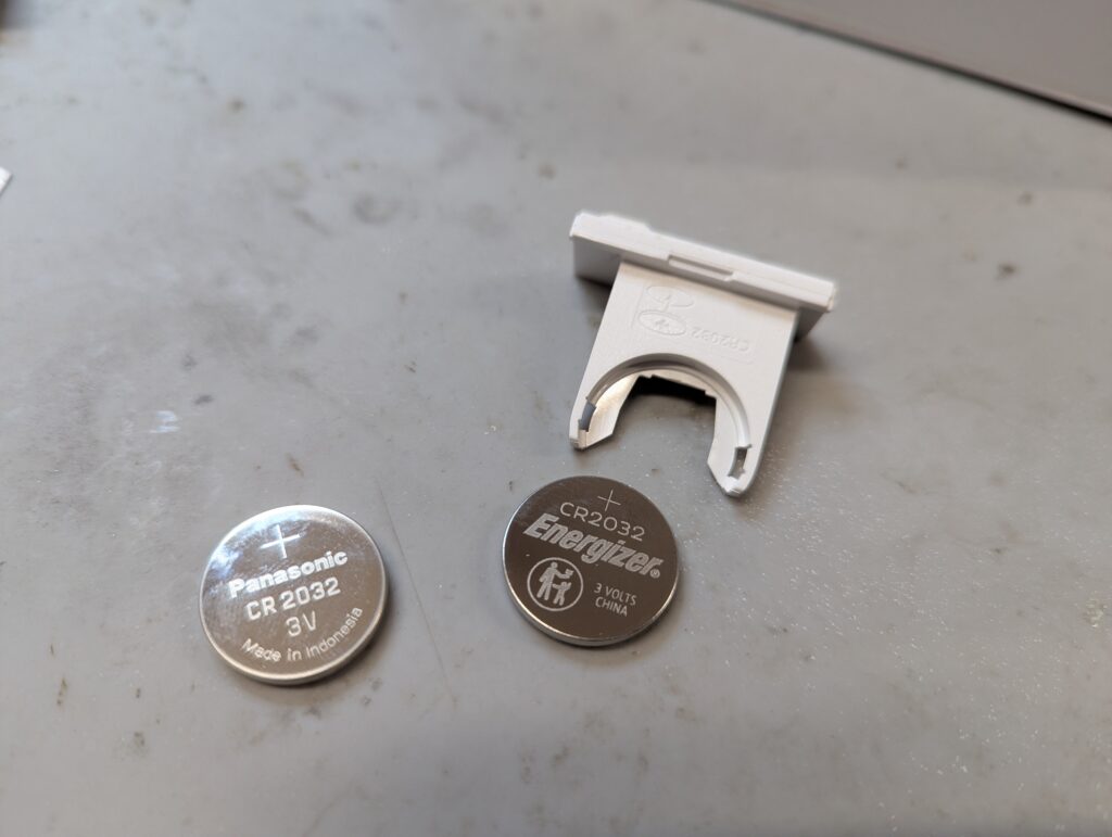
As agreed with the customer, I also installed new port flaps as the ones from this console were missing. The battery was also replaced as the one in the console was dangerously low.